Micromouse is not really like any other robotics competition as I would see. It’s kind of a hobby that someone can master throughout his/her life. Starting from ground up, learning from the basics, there’s long journey to be discovered. All of the great champions in international micromouse competitions have started from the very basics. Even though we see the complex robots build by them now, they all have a success story behind them.
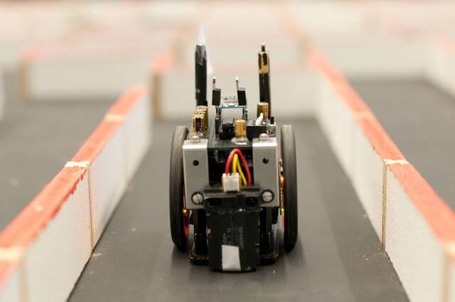
This is the first micromouse robot made by “GreenYee” and his team ; the all-time micromouse champion in USA and the founder of Micromouse USA website. It’s not all about doing everything perfect at the first try, but what really matters is the improvement over time.
The article series of “getting started in the micromouse journey” is written with the intention of sharing how team “CircuitBreakers” started its journey of micromouse. In this particular article, I will provide some insight about our first micromouse robot “වේග බට්ටා V1.0”.
We started designing our first micromouse robot back in 2018 to participate in the undergraduate level of “SLIIT Robofest 2018”. After we did our initial research on making micromouse, we have realized some basic aspects to be covered initially.
- Finding good hardware and build the robot
- Implement and test basic robot functions; turning, moving cells and etc
- Implementing flood fill algorithm
- Tuning and saving the shortest path
Let’s move to each aspect in detail.
1# Finding good hardware and build the robot
Here is the list of components we have used to design our robot.
-
Pololu 1200rpm HPCB 6V dual shaft micro metal motors x 2 – These motors are small and easy to control. We had to use custom pwm function to control these motors because they were too fast. For the V2.0 we have used a slower rpm of the same motor for easier control. (Link)
-
Pololu magnetic encoder pair kit for micro metal gear motors – These encoders are a good solution to measure distance travelled by the robot. 12 CPR resolution is reasonable to measure distances accurately. (Link)
-
Arduino Nano micro controller as the MCU – We chose Arduino platform as a good starting point to make a micromouse robot as we were young and inexperienced in this field at the beginning. Considering the smaller form factor we chose Arduino Nano as our solution. (Link)
-
Dual MC33926 Motor Driver Carrier – I had purchased this motor driver previously. Therefore, I used this for the micromouse robot. Any good quality, low power motor controller can be used. But be aware when using low quality L29xx motor controllers as the responsiveness of the robot might be affected by it. (Link)
-
MPU6050 Module – This is an entry range gyroscope which will suite for types all robotics applications. Other than being very cost effective, this gyro has some very unique features that other higher priced modules lack which I’m planning to cover in another article in the future. (Link)
-
Sharp IR distance sensors – These sensors can provide accurate distance measurements even the surface is angled and aren’t affected by the environment, object color or surface.
a. 4-30cm Distance sensor – These sensors were used to measure distance to the walls in front and align the robot correctly before a turn (Link)
b. 2-15cm Distance sensor – These sensors were used to measure distance to the walls and align the robot parallel to the walls of the maze (Link)
-
5V Buzzer – This came in handy as a debugging signal where we used as an auditory feedback for testing the robot. As the Arduino Nano has a smaller memory, we weren’t able to connect an OLED display for visual feedback, therefore using a buzzer was an alternative.
-
Button Panel – This consist of 3 programmable buttons + reset button of the MCU. This button panel has enabled to include several test programs to the robot to check all the basic functions without uploading several programs.
-
1200mAh 7.4V lithium ion battery – Using 7.4v battery, producing 5v and 6v for the sensors and motors can be easily done using step down convertors.
-
Step down convertors – Two separate step down convertors were used to provide 5V for the MCU and sensors, 6V for the motor driver.
a. LM2596 Module – 6V step down convertor
b. Mini DC 5v 360 Buck Convetor – 5v step down convertor
-
HC-05 Bluetooth Module – For testing the floodfill algorithm, we have used a Bluetooth module where we can send information to a mobile phone or laptop.
-
Pololu wheels 32x7mm Pair - we used these small wheels to suite the small form factor of our robot. smaller wheels give much more control over the speed. (Link)
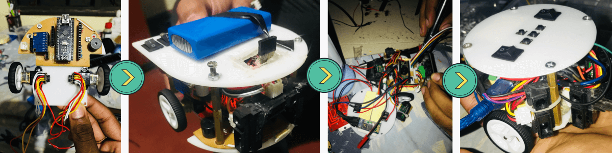
We have first started with a 10x10cm^2 design and moved to a circular 8x8cm^2 design where we placed motors in the middle of the robot for easier turning of the robot without changing the turning axis.
There are a lot to discuss when it comes to the testing and programming a micromouse robot. Therefore, rest of the stages will be discussed in the future articles in this series with the introduction of our next robot “වේග බට්ටා V2.0” in 2019.
Here’s a video of our robot performing at the finals of “SLIIT Robofest 2018” competition. Hope you learned something out of my first article in the article series of “Getting started in the micromouse journey”.
Always keep in mind to be unique, start slow and grow with time!
Please add your suggestions and questions below to improve my future articles. Good luck making your first micromouse robot. Thank You!
